How To File Fit and Install Piston Rings
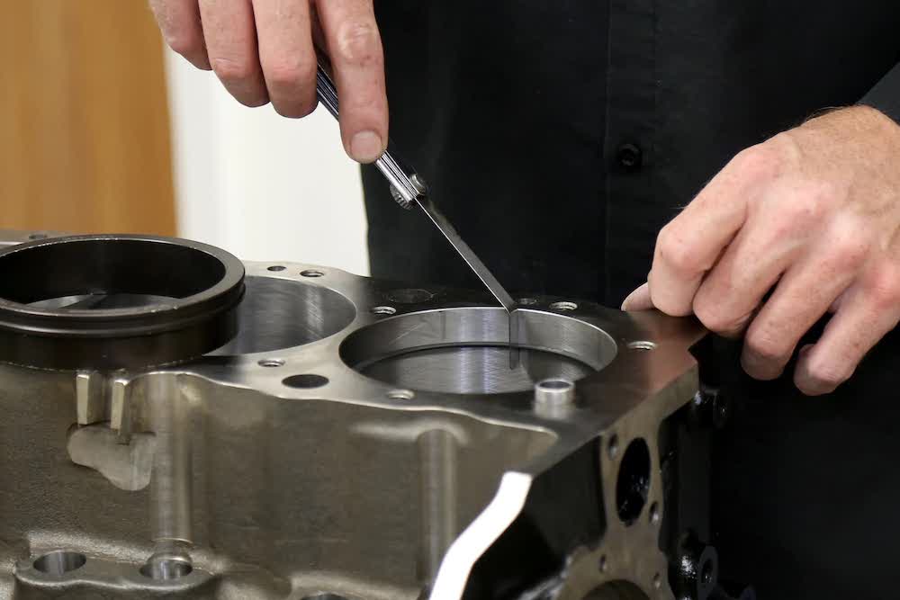
Gapping and correctly installing piston rings is one of the most important parts of engine assembly. Here’s how to do it right.
Piston rings perform a number of duties in an engine: They seal combustion pressure and gases in the chamber, preventing them from passing by the piston and into the crankcase where they can only do harm. They stabilize the piston as it travels up and down the cylinder bore, help cool the piston by transferring heat into the block’s cylinder bore, and finally, they meter the film of oil on the bore surface during operation. Rings perform these functions under the most extreme conditions, which is why premium ring sets should always be used, with materials and designs matched to the intended application.
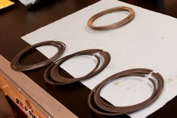
Piston rings come in sets for each piston. Ring type and material depend on the application and desired usage. The typical ring package consists of two compression rings and an oil ring.
The vast majority of piston and ring designs use a 3-ring package. The top two rings are called compression rings, and seal the combustion pressure. The bottom oil ring is actually made up of three different rings two narrow rails and one expander. The oil ring’s main function is to control the amount of oil that makes it between the piston and bore, which is necessary for lubrication and heat-transfer purposes. However, the second ring also provides a bit of oil control. Too much oil past the rings end up in the combustion chamber leading to all kinds of problems, making the oil control ring’s function critical.
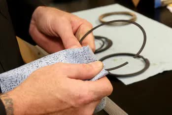
It’s a good idea to wipe down the rings as they’re being sorted. These tips and tricks are coming from CNC Motorsports in Brookings, South Dakota.
Piston compression rings seal to the bore via radial tension and combustion pressure, and each needs to be taken into consideration when fitting a set of rings to an engine. Radial tension is what you feel when you compress the ring by hand that push-back as the ring wants to reopen and it helps push the ring into the bore surface and seal the gap between piston and cylinder wall. In operation however, much of the sealing comes from combustion gases that slip behind the ring (between the ring and piston groove), and push the ring away from the piston and into the bore.
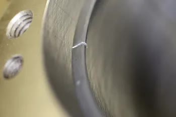
Piston rings expand due to the heat of combustion which closes the end gap. Too little clearance and the ring ends will butt, causing damage.
The most critical thing to check when installing piston rings is the end-gap. Ring end-gaps must be properly set to make sure the gap allows minimum combustion pressure to pass between piston and bore at operating temperature. A ring must have a split in it to allow installation on the piston, but also to provide room for expansion. This gap should be as small as possible during operation to seal as much combustion pressure in the chamber as possible, but large enough to keep the ring ends from touching when they expand due to combustion heat. This is called butting and can cause catastrophic piston failure.
On many performance applications, Wiseco includes file-fit rings, which are designed with very small end gaps that must be filed to fit in the bore for proper end gap for the application. To check the gap, the ring should be placed into the bore (without the piston) and squared up so that it’s level, using a ring-squaring tool. The cylinder bore must be honed to the final size before ring gap can be checked. Once the ring is in the bore, use a feeler gauge to check the gap.
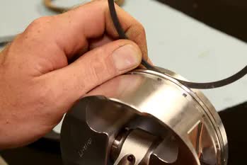
Ring side clearance is the space between the piston’s ring land and the ring itself. You don’t have to install the ring on the piston to check side clearance, you can just slip the ring in the groove and measure the clearance with a feeler gauge. While the ring is positioned in the groove, check to make sure the ring width itself isn’t deeper than the groove. This is known as backspacing.
To adjust the gap, the ring must be filed. You can use a flat file secured in a vise or a mechanical/electric ring filer to make the job easier and more precise. Make sure to file from the outside of the ring to the inside as this prevents chipping of the ring face and potential coatings. Make sure the cuts are straight by compressing the ring and holding it up to the light to look at the gap. If it is not perfectly straight, work the gap a bit with the file, making sure you are not opening it up more than the final gap required.
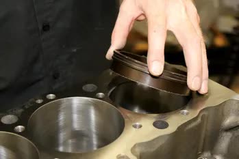
Use a ring squaring tool to seat the piston ring squarely in the bore, and a feeler gauge to check its gap. Check the gap often and grind slowly to prevent ruining the ring.
When filing the rings, sneak up on the final gap. Go slowly, removing minimal material at a time and re-checking the gap often. Remember, you can’t put the material back.
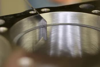
Use a feeler gauge to determine the preliminary ring gap. This process needs to be repeated for every ring, including the oil ring.
In ideal operation, the ring end gaps will be near zero to trap all of the combustion pressure in the chamber. But, don’t be tempted to run ring end gaps smaller than the recommended spec (included with all ring sets). The potential for ring butting and damage far outweighs any potential power gains.
The gap is adjusted by filing the ends of the ring. The cheapest method is clamping a file in a vise and running the ring across the face. There are two types of dedicated ring filers: hand-drive and motorized. This shop uses hand filers but modifies them to spin with a drill when desired.
As for installation orders, the top and second rings look very similar to each other at first glance, but their designs are often quite different.
The top ring is subject to the most intense heat and pressure, and the second ring is its backup and does double-duty metering oil that makes it past the lower, oil ring.
Grind slow and make sure the gap is perpendicular to the bore and not angled (Right)
Because of this, their designs are sometimes different, so you need to make sure the right ring goes in the right piston groove. Ring sets identify the top and second rings, usually by markings on the top of the ring surface, but this should always be clarified either by the manufacturer directly of the provided instruction sheet.
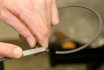
Use a file to deburr the rings. A rogue burr can scrape and scar the cylinder of a freshly honed engine.
In regards to the perfect end gap for your particular engine. The topic has been extremely scienced out. Included with every ring set is an application chart that takes into account bore diameter, application, and suggested gap. A naturally aspirated engine and a nitrous engine, for example, would have different end gaps, even if they had identical bores.
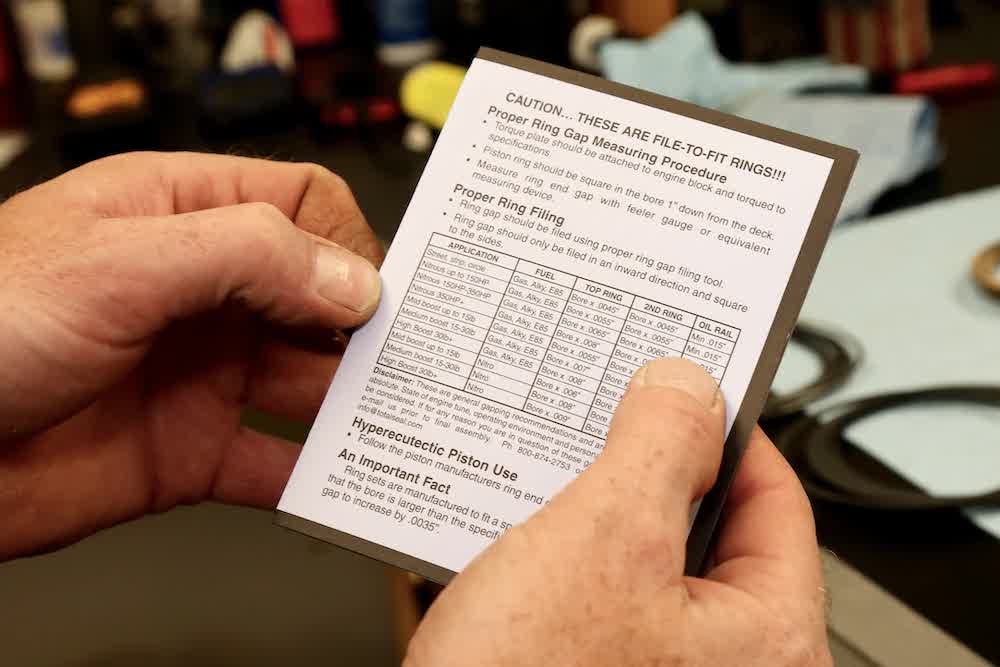
Check the instructions from the piston manufacturer to determine the proper ring gap for the application. Power adder engines will require larger end gaps than normally aspirated engines.
The nitrous engine will generate more heat, which cause the rings to expand more, hence they will need a larger gap. Forced induction images have a similar effect on ring end gap. To calculate the right end gap for your engine. Multiply the suggested clearance by your cylinder bore diameter. For example: a street strip application with a 4.030in bore has a recommended clearance of bore x .0045in.
By multiplying 4.030in by .0045in we get an end gap of .018in for the top ring. From there, we can hit the ring grinder and start making some clearance.
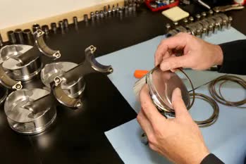
Once the rings are all gapped correctly, the rings can be assembled onto the pistons and installed into the engine.


